Goal
The goal for this project was to create a prototype finger drum glove with pressure sensors in the fingers to control a software drum synthesizer.
Motivation
This project was motivated by a desire to find a more natural method of interacting with common MIDI triggers. By having discrete pads and a spaced layout, the interaction can sometimes be awkward.

I am a drummer and also tap compulsively. However, I have always found trigger pads awkward to use. They frustrate me. I wanted a controller that would accept my style of finger tapping (which I can do very fast and with intricate patterns) which does not translate well to MIDI trigger pads. The Finger Triggers are a solution to that problem.
Design rationale
In thinking about the MIDI trigger pads, I considered the possibility of inverting the usual implementation. Instead of putting the sensor on the surface being struck, I decided to put the sensor on the finger doing the striking. In doing this, the user can achieve a new level of freedom in expression since they can strike any surface to trigger MIDI notes.
Design rationale with an eye toward the future
After successfully designing and refining a set of finger triggers, a further enhancement to the system that could be implemented is re-introducing a performance surface. Ideally this would be a pressure-sensitive multi-touch surface. When combined with the finger triggers, this would form a more complete trigger sensor system that can not only detect location, but also match the trigger location to which finger is being used. This would allow for the design of more nuanced mappings between input and output.
Currently, the most sophisticated MIDI controllers commercially available provide such a multi-touch surface, but at present none of them can detect any information about what is interacting with them. When playing an acoustic percussion instrument, it is easy to change the timbre by hitting it with a different stick or mallet, but this not the case with drum triggers. By developing methods of detecting what is hitting a sensing surface (by starting here with the fingers), an even more sophisticated and nuanced MIDI controller can be designed.
In addition to pairing the finger triggers with another sensor, they could also be paired with an acoustic instrument, such as hand drums, to gather performance information. They could then be used to dynamically control electroacoustic processing based on the live performance data. Applications of this nature are wide open and limited mainly by the user’s imagination.
The project documented below is a first step toward created the proposed system.
Design principles
This device has a low threshold for usability due to being so intuitive to use. You tap your fingers and it triggers a sound. However, the trigger mapping can be reprogrammed, with moderate Max/MSP experience, to trigger whatever the user may like so it is quite flexible. Similar to other music-making methods, there is a plenty of room for mastery. This controller mimics the playing styles of many hand drums – especially those from Middle Eastern or Southern Asian traditions.
In terms of levels of creativity, this interface supports mini-c and small-c creativity, but it also has the potential to reach pro-c and Big-C. It can operate at as low of a level as mini-c creativity for personal enjoyment, but with refinement could potentially be used to good effect in professional performance. I also do think it could make it to Big-C level creativity by influencing a next generation of MIDI controllers that sense information on both sides of the user/interface relationship.
Demo video
Materials
- Arduino Uno microcontroller
- Velostat sheet
- This is a sheet of thin, plastic-like material that changes its electrical resistance as pressure is applied to it
- Conductive fabric
- Scrap fabric
- Resistors
- 1 kΩ resistors work fine
- Breadboard
- Jumper cables
- Wires with alligator clips
- Thin cardboard
- Cheap glove
- Double stick tape
Tools
- Needle
- Thread
- Scissors
Software
- Arduino IDE
- Max/MSP
Making an FSR pad
1. To make a force sensing resistor (FSR) pad, you will need two pieces of cardboard cut into 4 cm squares, a 4 cm square piece of velostat, and two pieces of conductive fabric. Cut the conductive fabric so that there is a main portion that is a square smaller than the velostat square (about 3.5 cm) with a “lead” hanging off one side.
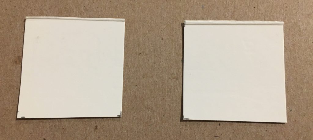

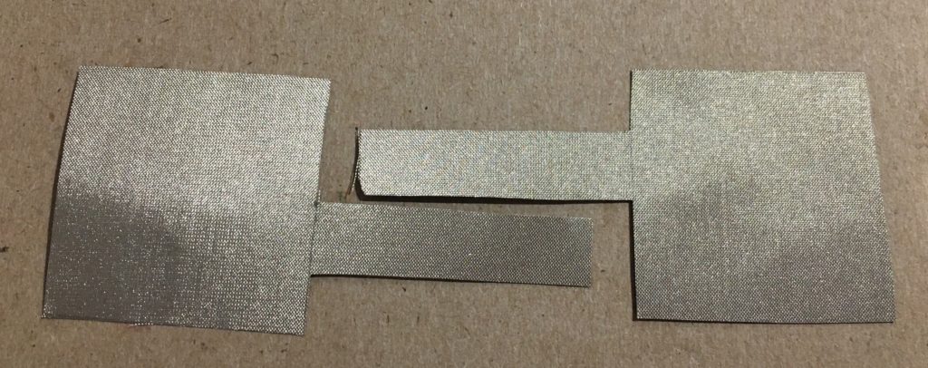
2. Make a sandwich of the materials like this: cardboard on the outsides, then the conductive fabric squares with the leads hanging out in different directions, and then the piece of velostat in the middle. It’s important that the two pieces of conductive fabric do not touch at all.
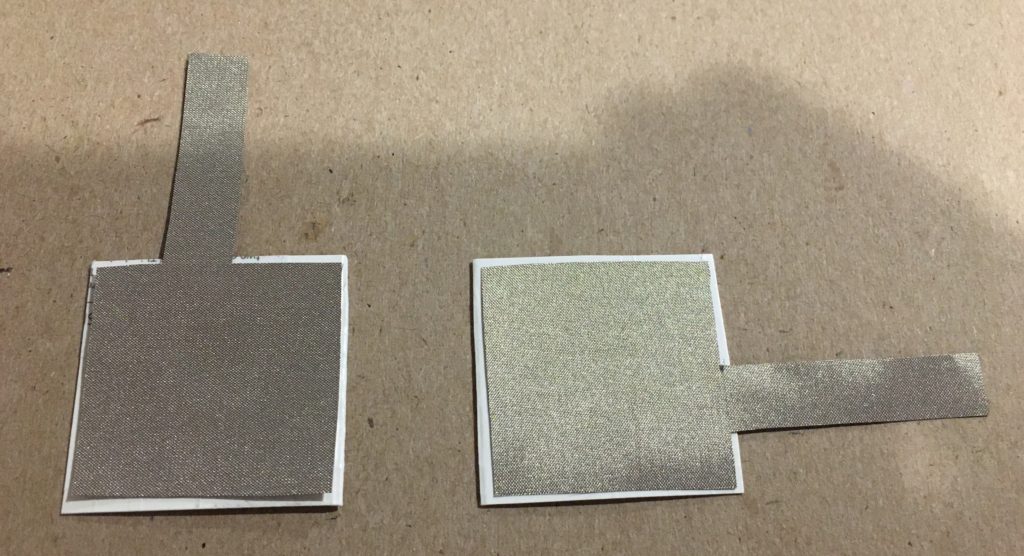
Tip: you can use double sided tape to attach the conductive fabric to the cardboard so that it will not shift around.
3. Once the sandwich is made, tape around the outside to keep the insides from coming apart. How to connect this to the Arduino will be explained below.
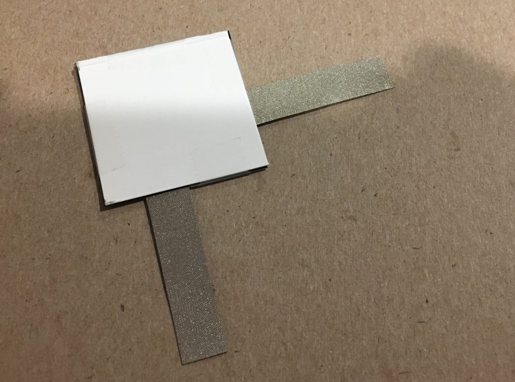
How to attach an FSR to a glove
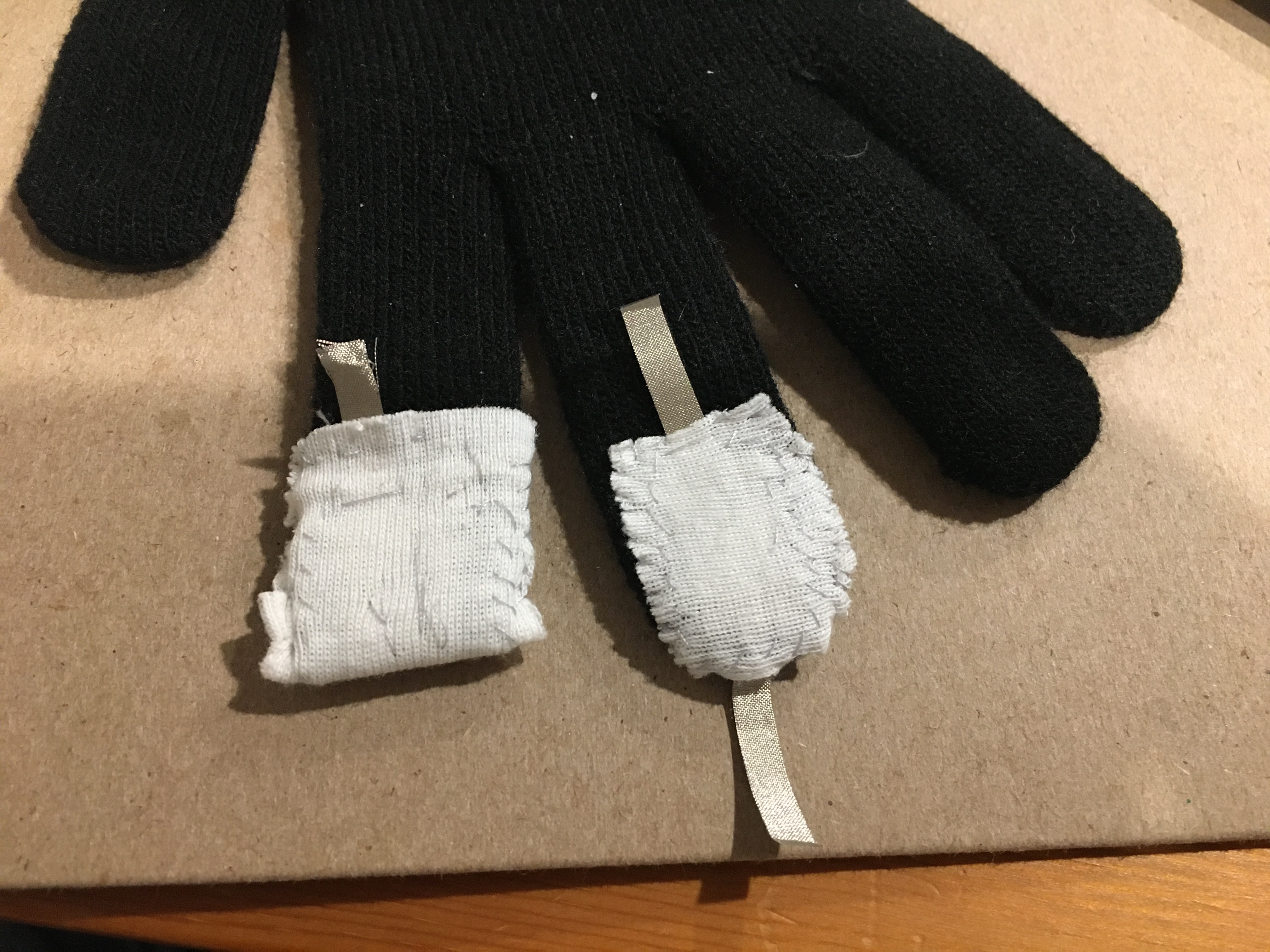
This is very similar to making a regular FSR pad as above, but modified to sew it into the fingertip of a glove. This makes the process more delicate and challenging, but the principles are the same.
1. Cut two pieces of conductive fabric into 1 x 2 cm rectangles with a 2-3 cm lead tab hanging off one of the short sides. Cut a piece of velostat to be slightly larger than the 1 cm x 2 cm rectangles (~1.5 x 2.5 cm). Finally, cut a piece of scrap fabric to be larger than the velostate (~ 2 x 3 cm).
2. Carefully sew one pieces of the conductive fabric to the fingertip of the glove with the lead tab going along the length of the finger. If the edge of the conductive fabric is aligned with the seam of the glove, then the conductive fabric will cover both the fingertip and the finger pad when the glove is worn.
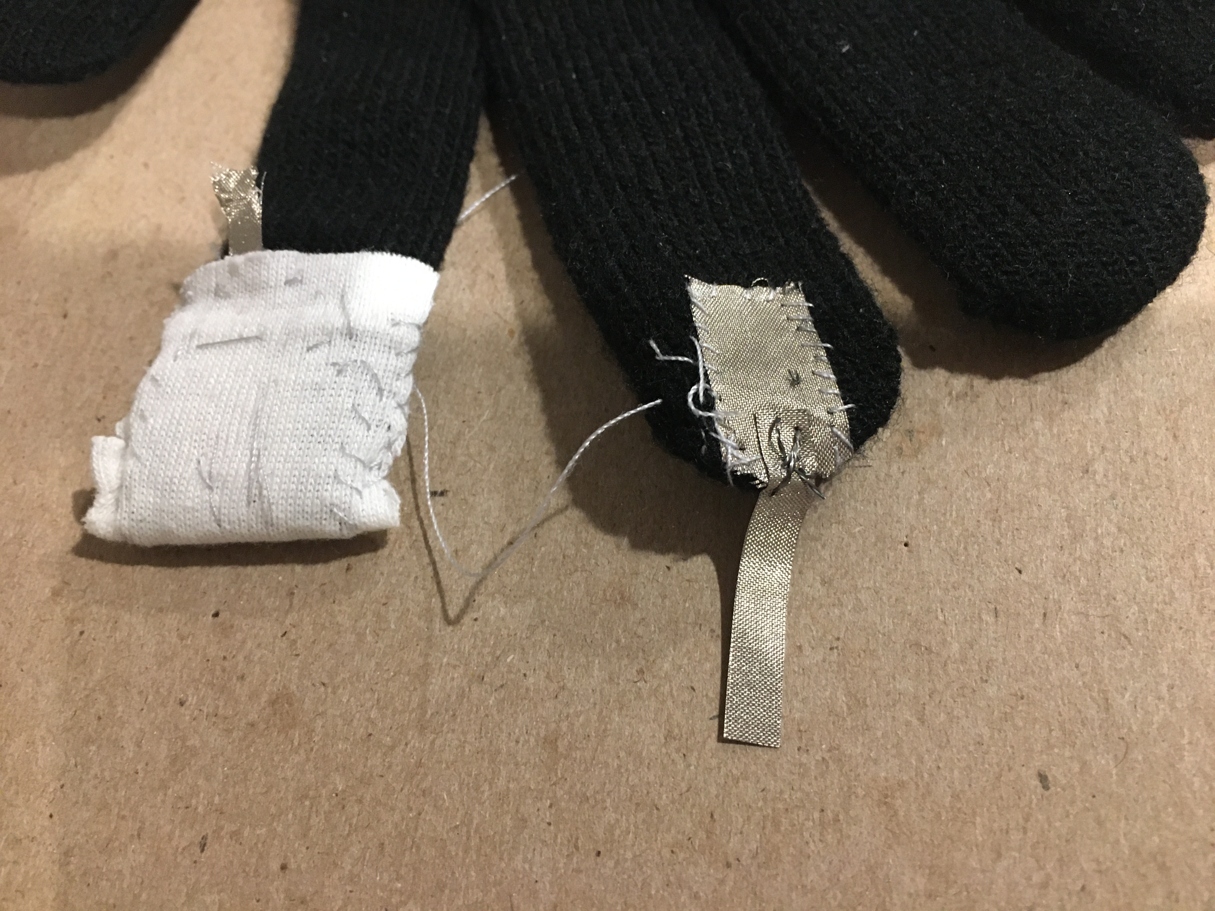
3. Sew the other piece of conductive fabric to the center of the piece of scrap fabric with the lead tab hanging out.
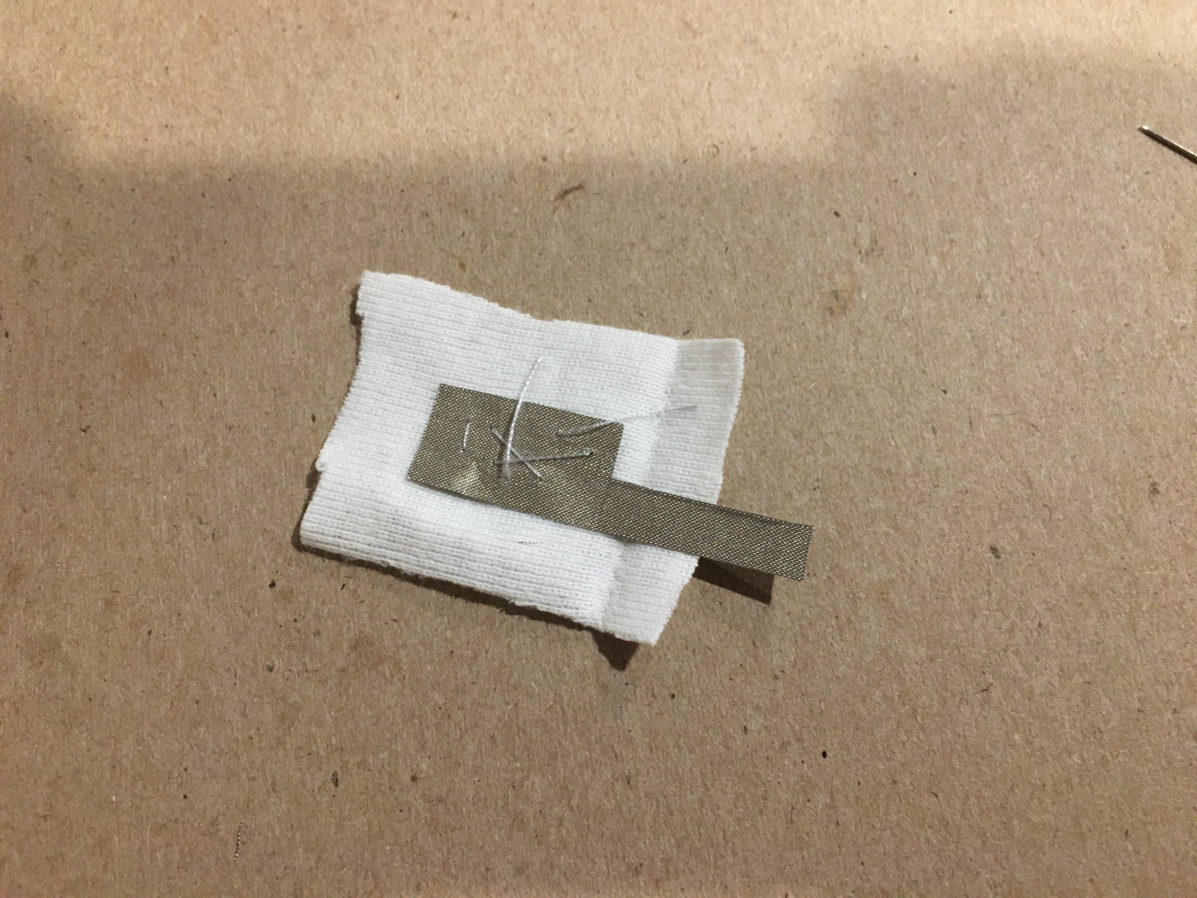
4. Carefully sew the velostat sheet to the scrap fabric so that the conductive fabric is completely covered (other than the lead tab). This will be most effective if the sewing is to the outside of the conductive fabric since this will puncture the velostat.
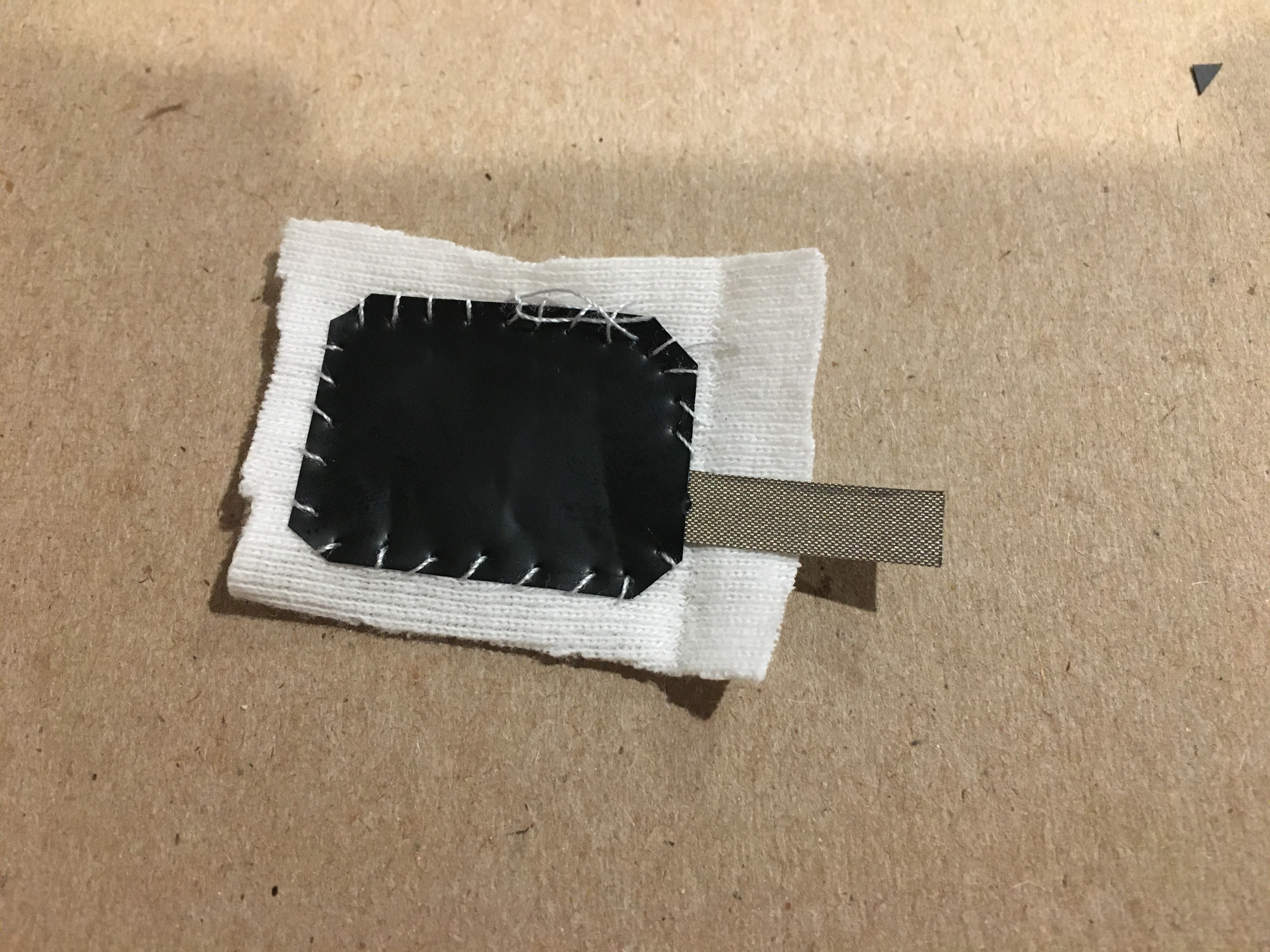
5. Carefully sew the scrap fabric with the conductive fabric and velostat pad to the glove finger so that the velostat is between the two pieces of conductive fabric and the leads hang out in opposite directions.
How to wire an FSR to the Arduino
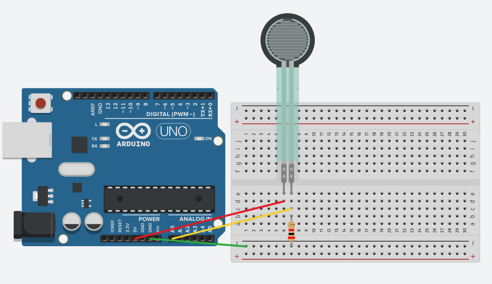
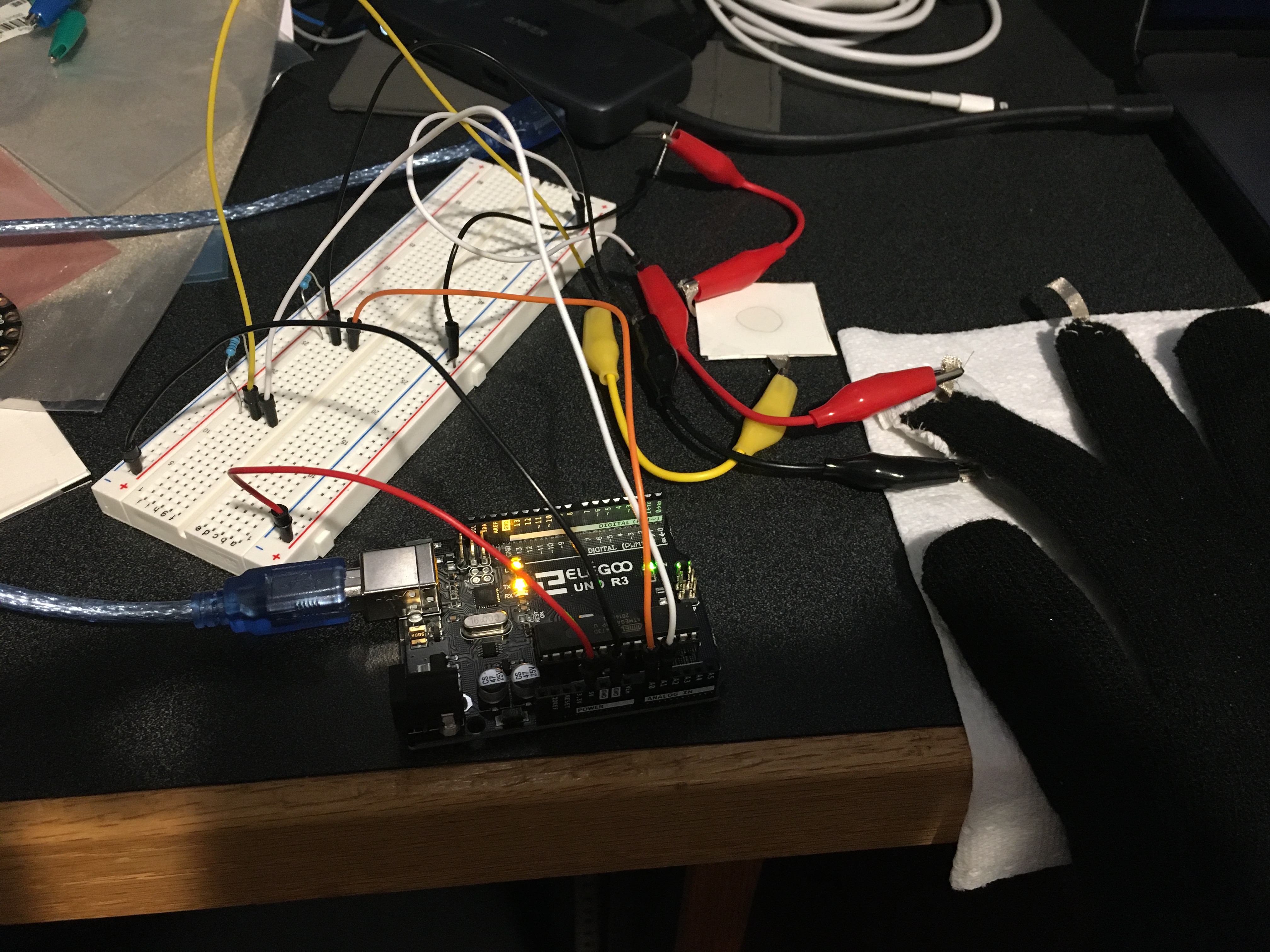
The image above shows how to connect a pressure sensor to an Arduino using a breadboard. Here is a breakdown of the steps:
- Connect the 5V power to one of the leads from the pressure sensor.
- Connect the other lead to one of the analog input pins of the Arduino. In the example it is connected to pin A0.
- To the same lead of the FSR that is connected to the analog input connect a resistor (1 kΩ). Connect the other end of the resistor to the ground.
- Some resources recommend using a 2 kΩ resistor, but for my setup, I found that using 1 kΩ resistors gave a wider usable range. The best resistor values can depend on the situation and specific materials so test several to see which yields the best results.
- For my prototype, I used alligator clips to attach the conductive fabric to jumper cables from the breadboard. This method is not ideal, but works for prototyping.
- In future versions, I will experiment with attaching the microcontroller directly to the glove and connecting wires to that. The Arduino Uno, however, is too big and heavy for that. An option I will explore is the Adafruit Flora – which is designed to be used in wearable electronics projects and using conductive thread instead of actual wires.
Reading the pressure sensor input data on the Arduino
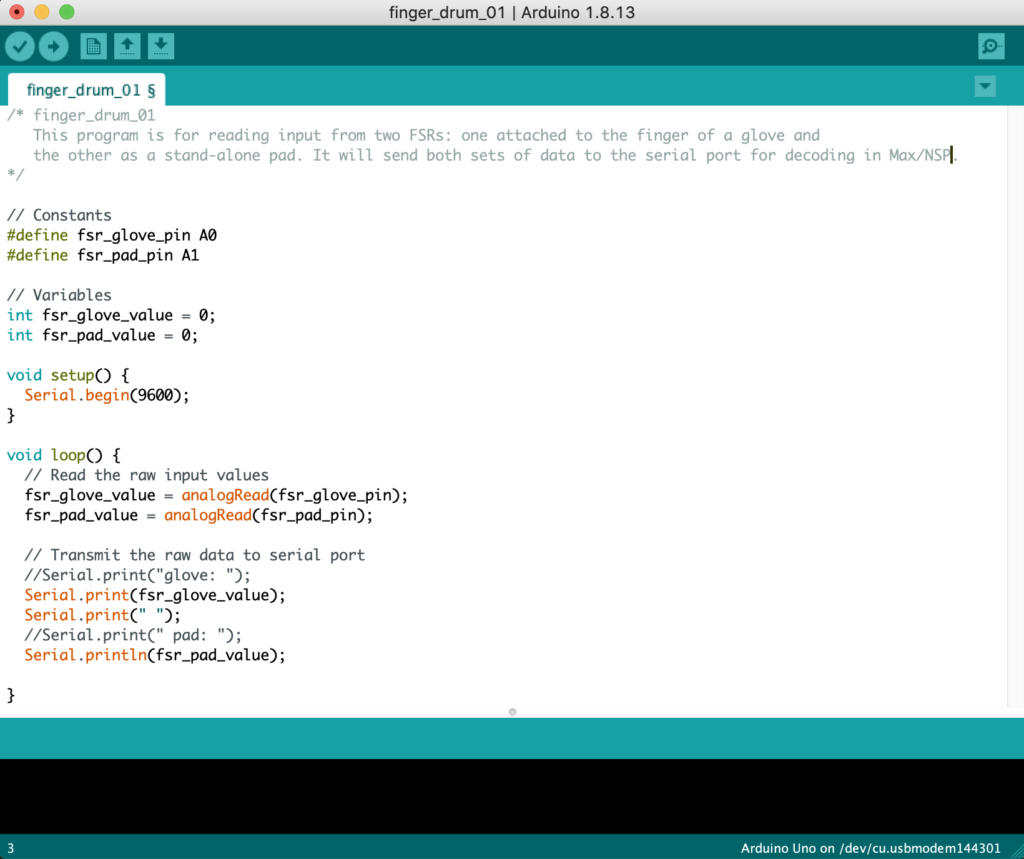
Reading the input of the pressure sensor with the Arduino is requires only a simple program. For my project, I sent the input readings to the serial port for decoding in Max/MSP.
- Outside of
setup()andloop()functions, define an input pin using#define input_pin A0. We will also need to define two integer variables to store the pin input values withint input_value = 0;. - In the
setup()function, all that is need isSerial.begin(9600);to start serial port output. - In the
loop()function, you can read from the input pin by typinginput_value = analogRead(input_pin);. - This value is then sent to the serial port using the command
Serial.print(input_value);. If sending multiple values (as I am with a finger sensor and a pad), include a space between the values withSerial.print(" ");. For the final value, use the commandSerial.println(input_value);to add a carriage return before the next read.
Once this is done, the Arduino will be sending the input values as integers between 0 and 1023 to the serial port. This can be tested with the serial port monitor in the Arduino IDE. This data will be parsed in Max/MSP and used to trigger drum sounds.
Here is a screenshot of my program for reading values from two pressure sensors:
Decoding serial information in Max/MSP
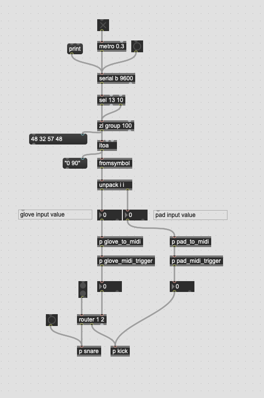
Instead of converting the input values to MIDI on the Arduino and sending that information to the computer, I decided to send the raw input values and process that within Max. Doing the processing inside of Max allows the user to adjust sensitivities and settings dynamically and get clear visual feedback. While two-way communication with the Arduino is possible, it can get complicated quickly.
In order to read serial data in Max, use the serial object with the appropriate port and baud setting to match the Arduino. Serial messages are sent as series of integers that end with a 13 and a 10. Using the sequence of objects sel 13 10, zl group 100, itoa, fromsymbol, and finally unpack i i will result in decoding the analog input values as integers that can then be used for further processing in Max. This is process is shown in the image below.
Converting to MIDI in Max
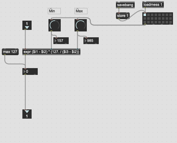
In order to convert to MIDI, we need to set two things: a minimum value (since the minimum read value may not be 0) and a maximum value (which may not be 1023). The user can adjust adjust the minimum value to create some space to prevent false triggers. They can also adjust the maximum value to customize the sensitivity. Once the minimum and maximum values are set, converting to a 7-bit value (0 to 127) can be accomplished with this formula: midi = 127 * (input_value - min) / (max - min) and rounding to the nearest integer. You can see this implementing in a Max below. This is the coded in the p pad_to_midi subpatch object.
Triggering sound
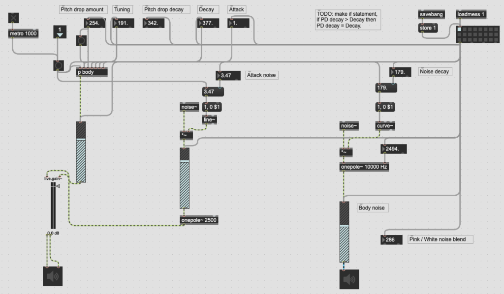
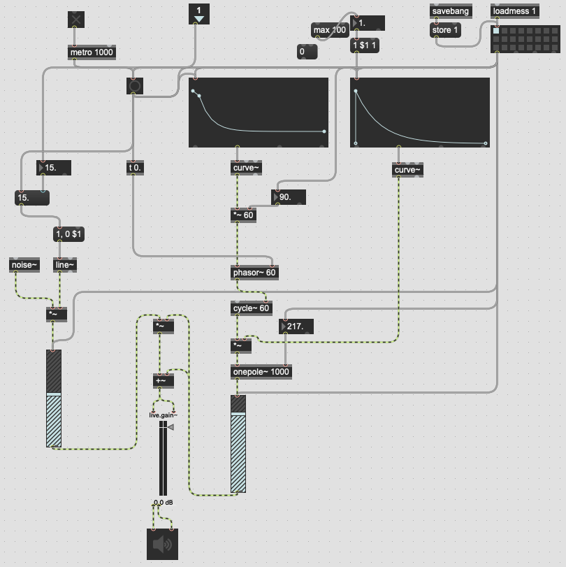
Once MIDI conversion is done, whatever sounds the users like may be triggered with it. In my program, I programmed synthesized kick and snare sounds. I will not explain the concepts behind how these synthesis programs work, but will include images of their implementation the can be used to replicate the functionality below.
Future plans
Future plans for this project involve enhancing two aspects of it: one, improving the gloves, and two, creating a pressure sensing location-aware surface.
In terms of improvements to the gloves, there are several ideas to test. First is to attempt a more e-textile approach as documented in a SIGCHI paper by Aigner, et al [1]. They used conductive thread to embroider a resistive fabric onto a glove. This approach appears promising, but is difficult without a high quality (possibly industrial-level) embroidery machine. However, even with sewn on pressure sensors, performance and usability should improve by replacing the alligator clips and breadboard with soldered connections to a microcontroller attached to the glove. A candidate for this method is the Adafruit Flora microcontroller. One disadvantage of this is that the Flora only has four analog input pins. However, it does have a compatible secondary board for using with Bluetooth Low Energy. Another candidate is an ESP32 microcontroller. These are powerful boards that usually come with built-in wifi and Bluetooth, but are not designed specifically for use as a wearable microcontroller like the Flora.
There is also a project on the Adafruit website from 2014 creating similar MIDI trigger gloves. I found this project after designing the system above while I was considering the Flora platform for a next iteration. The main difference between my implementation and the Adafruit project is that I use pressure sensors and their project uses piezo elements. Since the piezos are self-contained in small plastic housings, they are easier to attach to gloves. However, piezos are much bulkier, are more sensitive to false triggers and more susceptible to cross-talk. Piezos are a convenient input method for a project like theirs, but I believe ultimately that pressure sensors will be the better choice of sensor for my ultimate goals.
My tentative plan for creating a pressure-sensitive multi-touch surface is to use an entire velostat sheet (12″ x 12″) that is lined on one side with horizontal copper strips and vertical copper strips on the other. Then using multiplexors to interface with the two sets of strips, pressure and location can be determined. Combining location information from a pad of this nature with finger information from the glove would open up interesting new arenas of advanced interaction between the user and computer that is not possible with a one-sided sensing system. Since my system is using a purpose-built Max/MSP program, it can be further customized to take advantage of additional information sources to implement more sophisticated behaviors and reactions to user inputs.
Code: All of the code used in this project is available on GitHub.
References.
- Aigner R, Pointner A, Preindl T, Parzer P, Haller M. Embroidered resistive pressure sensors: A novel approach for textile interfaces. InProceedings of the 2020 CHI Conference on Human Factors in Computing Systems 2020 Apr 21 (pp. 1-13).
- Adafruit Flora MIDI Drum Glove. https://learn.adafruit.com/midi-drum-glove. Published 18 June, 2014. Accessed 7 Feb, 2020.